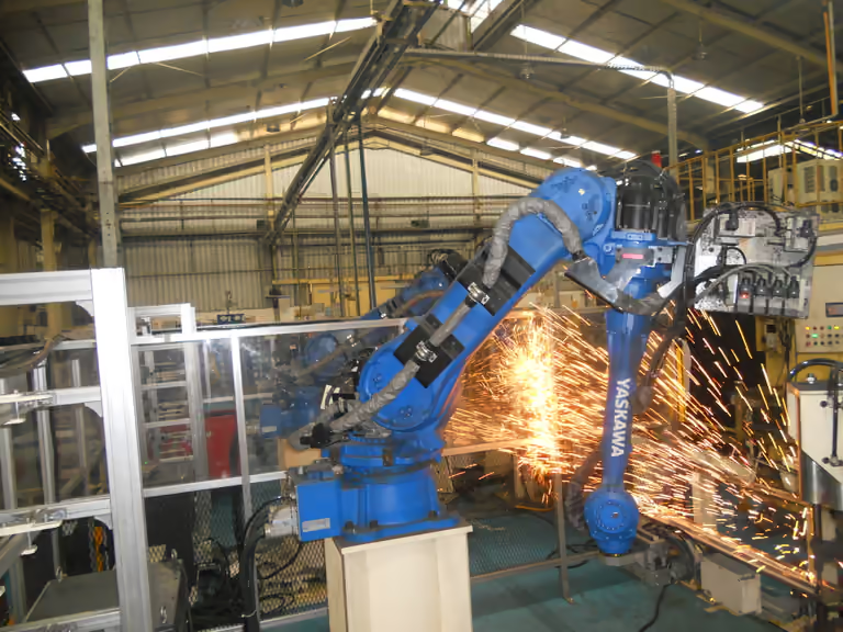
Represent kinematics
Model axes, travel limits and moving assemblies using your machine documentation.

ZuberCAM / Services
A machine model shows machining operations in context. ZuberCAM builds and adapts simulation models with the kinematics, tools and fixtures of your application.
Model axes, travel limits and moving assemblies using your machine documentation.
Include tools, holders, fixtures and part positions required by the agreed verification tasks.
Review motion and potential conflicts virtually. Results depend on the model, data quality and simulation scope.

01 / Project inputs
The key details are enough for initial contact. We will discuss which documents, files or test parts are needed and how you can provide them.
Discuss your taskReview the application, existing systems and required functions.
Agree input data, implementation and representative test tasks.
Compare the results with the agreed requirements.
Discuss documentation, operation and suitable training.
Frequently asked questions
A toolpath describes planned movements. A machine model adds the geometry and kinematics of the machine, tools and workholding. Available checks depend on the model scope.
Changed geometries and configurations must be reflected in the data used. We discuss what you can maintain yourself and when the model needs adapting.
We assess your actual machine, control, software version and required functions. A manufacturer name alone is not enough for a reliable assessment.
Existing projects and documentation are a useful starting point. Together we determine what can be reused and which additional information is needed.
Effort depends on functions, available data and agreed tests. After technical scoping, you receive a quotation describing scope and proposed process.
We compare representative test cases against your requirements. NC output requires technical review and controlled trials during commissioning. Simulation alone does not replace these steps.
02 / Related topics
Personal support. In Switzerland.
Tell us about your setup and goal. Together we will agree the right next step.