Scope the application
Review the part, material, machining process and current challenges together.

ZuberCAM / Services
We support your milling programming in Ency, from 2.5D and three-axis tasks to indexed or simultaneous five-axis machining. CAM workflows, post-processing, simulation and training are tailored to your parts and machine.
Review the part, material, machining process and current challenges together.
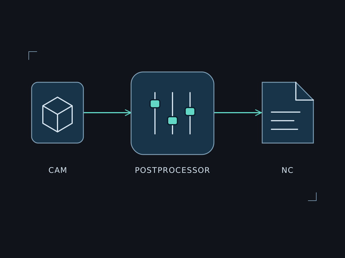
Align strategies, post-processor and machine model with the agreed requirements.
Explain workflows, agree test tasks and select suitable training.
Practice and technology
We support CAM programming for your milling tasks. A representative part helps identify the required strategies, setups and machine functions. Geometry, accessibility, tooling and the available CAM configuration determine the approach.
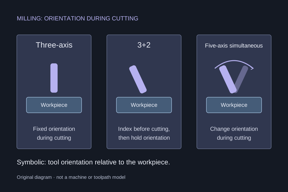
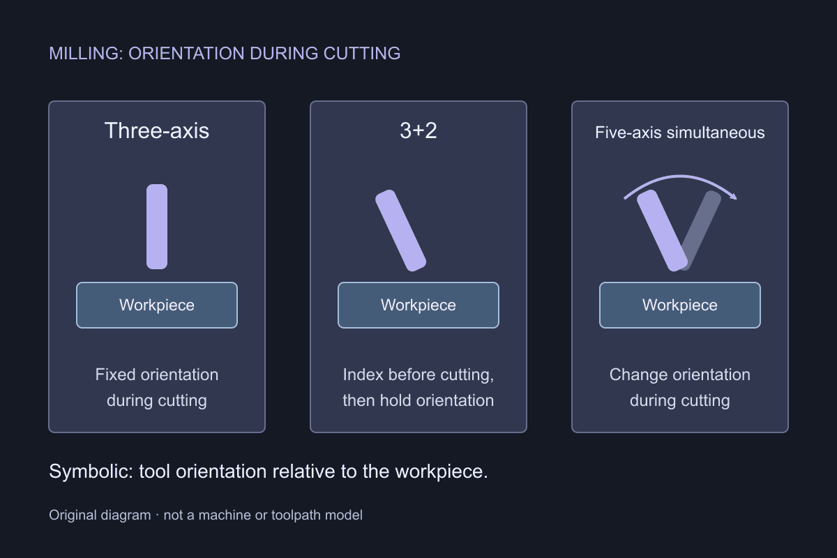
Machine pockets, contours, holes and 3D surfaces with suitable strategies. During three-axis cutting, X, Y and Z can move together while the tool orientation stays fixed within the operation.
The rotary axes orient the tool relative to the workpiece before cutting and hold that orientation during the subsequent three-axis operation. This allows multi-sided machining on a five-axis machine, but does not constitute a simultaneous five-axis toolpath.
Tool orientation can change during cutting. Strategy, CAM licence, kinematics, post-processor and control options must support the chosen approach. Simultaneous machining is not necessary for every surface.
01 / Project inputs
The key details are enough for initial contact. We will discuss which documents, files or test parts are needed and how you can provide them.
Discuss your taskReview the application, existing systems and required functions.
Agree input data, implementation and representative test tasks.
Compare the results with the agreed requirements.
Discuss documentation, operation and suitable training.
Frequently asked questions
No. Many tasks can be completed with three-axis or indexed 3+2 machining. The choice depends on geometry, tool access, workholding and the machine. We also assess the CAM licence against the strategies actually required.
We check whether it supports the planned operations, control options and actual machine configuration. Changes to control options or coordinate transformations may require adaptations and new tests.
We assess your actual machine, control, software version and required functions. A manufacturer name alone is not enough for a reliable assessment.
Existing projects and documentation are a useful starting point. Together we determine what can be reused and which additional information is needed.
Effort depends on functions, available data and agreed tests. After technical scoping, you receive a quotation describing scope and proposed process.
We compare representative test cases against your requirements. NC output requires technical review and controlled trials during commissioning. Simulation alone does not replace these steps.
02 / Related topics

Personal support. In Switzerland.
Tell us about your setup and goal. Together we will agree the right next step.